You cut the blank exactly to the drawing. You bend it. And the finished flange comes out 1.5 mm short.
Nothing was wrong with the machine, and nothing was wrong with the operator. The problem was the flat length, because sheet metal does not simply fold like paper. It stretches on the outside and compresses on the inside. If you don’t account for that, every bent part carries a small error, and parts with several bends carry several errors stacked together.
The bend allowance formula is how you fix that. It tells you how much flat material a bend consumes, so you can build the correct blank before the metal ever touches a press brake.
This guide explains the formula in plain language, shows two fully worked examples with real numbers, and covers the part most articles skip: how to find the right K-factor for your own material instead of guessing.
What bend allowance actually is
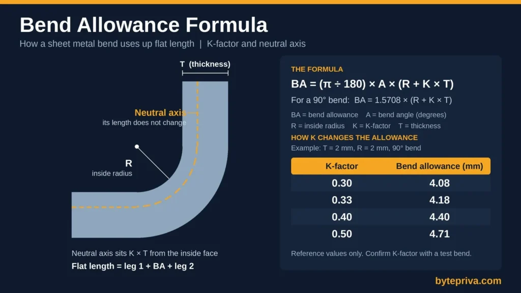
When a flat sheet is bent, the metal on the inside of the bend is squeezed and the metal on the outside is stretched. Somewhere between the two surfaces, there is a line that does neither. It keeps its original length. That line is called the neutral axis.
Bend allowance (BA) is the length of that neutral axis through the bend, in other words the arc length of the bend measured along it. Because the neutral axis doesn’t change length, it is the one reliable thing you can measure on both the flat blank and the finished part. That is why all flat-pattern maths is built around it.
The basic relationship is simple:
Flat length = leg 1 + bend allowance + leg 2
Here, “leg” means the straight part of each flange, measured up to the point where the bend begins. Add the legs and the bend allowance together and you get the length of the blank you need to cut.
The bend allowance formula
Here is the standard bend allowance formula, with the angle in degrees:
BA = (π ÷ 180) × A × (R + K × T)
- BA = bend allowance (mm or inches)
- A = bend angle in degrees
- R = inside bend radius
- K = K-factor
- T = material thickness
For a 90° bend, this simplifies nicely:
BA = (π ÷ 2) × (R + K × T), which is about 1.5708 × (R + K × T)
Two things are worth noticing. First, the term (R + K × T) is simply the radius of the neutral axis: the inside radius plus the distance from the inside surface to the neutral axis. Second, the bend allowance grows in direct proportion to the bend angle. A 45° bend uses half the allowance of a 90° bend, with everything else unchanged.
A quick note on the angle. The “bend angle” here means how far you turned the metal. A flat sheet has a bend angle of 0°, and a standard L-bracket has a bend angle of 90°. Some drawings give the included angle instead (the angle between the two flanges after bending). In that case, bend angle = 180° − included angle. Mixing these up is a very common source of wrong flat lengths.
K-factor: the number that decides everything
K-factor tells you where the neutral axis sits inside the thickness of the sheet. It is a ratio:
K = t ÷ T
where t is the distance from the inside surface to the neutral axis and T is the full thickness. A K-factor of 0.5 means the neutral axis is exactly in the middle. A K-factor of 0.33 means it sits one-third of the way in from the inside surface.
In practice, K-factor usually falls between about 0.3 and 0.5. It is not a fixed property of the material. It depends on the material, its thickness, the bend radius and the bending method. As a general trend, tighter bends and stronger materials tend to push the neutral axis closer to the inside surface, which means a lower K-factor. Gentler bends in softer metal tend to push it towards the middle.
That variation is exactly why no table of “K-factors by material” can be fully trusted for your shop. A figure such as 0.33 is a sensible starting point for mild steel, but it is a starting point and not a guarantee. Later in this article you’ll see how to find your own value.
Worked example 1: a simple L-bracket
Let’s put numbers to it. You need an L-bracket with these details:
- Material: mild steel sheet, thickness T = 2 mm
- Inside bend radius R = 2 mm
- Bend angle A = 90°
- K-factor = 0.33 (starting value)
- Outside flange dimensions on the drawing: 50 mm and 30 mm
Step 1: Bend allowance
BA = (π ÷ 180) × 90 × (2 + 0.33 × 2)
BA = 1.5708 × 2.66
BA = 4.18 mm
Step 2: Outside setback (OSSB)
The outside setback is the distance from the bend’s outside tangent point to the “virtual sharp” corner where the outside faces would meet. The formula is:
OSSB = tan(A ÷ 2) × (R + T)
For a 90° bend, tan(45°) = 1, so OSSB = R + T = 2 + 2 = 4 mm.
Step 3: Bend deduction (BD)
BD = 2 × OSSB − BA = 2 × 4 − 4.18 = 3.82 mm
Step 4: Flat length
Because the drawing gives outside dimensions, we subtract the bend deduction from their sum:
Flat length = 50 + 30 − 3.82 = 76.18 mm
You can double-check this a second way, using legs instead of outside dimensions. Each straight leg is the outside dimension minus the setback: 50 − 4 = 46 mm and 30 − 4 = 26 mm. Then 46 + 26 + 4.18 = 76.18 mm. Same answer, which is exactly what you want.
Bend allowance vs bend deduction vs outside setback
These three terms confuse almost everyone at first, so here is how they fit together.
| Term | What it means | When you use it |
|---|---|---|
| Bend allowance (BA) | Length of the neutral axis through the bend | When you know the straight leg lengths (measured to where the bend starts) |
| Outside setback (OSSB) | Distance from the start of the bend to the virtual sharp corner | A building block for bend deduction |
| Bend deduction (BD) | What you subtract from the sum of the outside dimensions to get the flat length | When the drawing gives outside dimensions, which is the most common case |
The link between them is: BD = 2 × OSSB − BA. They are not three different methods. They are the same physics, expressed in the way that suits how your drawing is dimensioned.
The practical rule is this: check how the drawing is dimensioned. If dimensions run to the outside faces, use bend deduction. If they run to the start of the bend, add the bend allowance. If you’re not sure which one your drawing uses, ask before cutting, because the difference is several millimetres per bend.
Worked example 2: a U-channel with two bends
Same material and settings as before (T = 2 mm, R = 2 mm, 90° bends, K = 0.33), so BD = 3.82 mm per bend.
The channel has a 40 mm web (the base) and two 25 mm flanges, all dimensioned to the outside faces.
Flat length = 25 + 40 + 25 − (2 × 3.82)
Flat length = 90 − 7.64
Flat length = 82.36 mm
Notice what happens: two bends take almost 7.7 mm off the sum of the dimensions. If you had ignored bend deduction and cut the blank at 90 mm, every finished part would be about 7.6 mm too long. That is the kind of error that causes holes to miss, parts not to fit, and an entire batch to be scrapped.
How much does a wrong K-factor really matter?
Quite a lot, and it adds up. Take the same 2 mm steel, 2 mm radius, 90° bend and see how the bend allowance moves as K changes:
| K-factor | Bend allowance (mm) |
|---|---|
| 0.30 | 4.08 |
| 0.33 | 4.18 |
| 0.40 | 4.40 |
| 0.50 | 4.71 |
Going from K = 0.30 to K = 0.50 changes the bend allowance by about 0.63 mm for a single bend. Because the outside setback doesn’t depend on K, the flat length shifts by exactly the same amount.
On a part with one bend, 0.6 mm might be within tolerance. On a part with six bends, the same assumption error becomes about 3.8 mm. That is why precision work needs a K-factor you have actually verified, and why “close enough” gets expensive on multi-bend parts.
How to find your own K-factor with a test bend
The most reliable way to get the right K-factor is also the cheapest: bend a scrap piece from the same sheet, using the same tools and method you’ll use on the real job.
- Cut a test strip and record its exact flat length (Lf).
- Bend it to 90° using your normal process.
- Measure the two outside flange lengths (A and B) on the bent piece.
- Measure the actual inside radius (R) and the material thickness (T). The radius you get comes from your tooling and process, so measure it instead of assuming the nominal value.
- Work backwards with these steps:
- BD = A + B − Lf
- BA = 2 × (R + T) − BD (for a 90° bend)
- K = (BA ÷ 1.5708 − R) ÷ T
Example with sample measurements: T = 2 mm, R = 2 mm, A = 50 mm, B = 30 mm, and the strip’s flat length was 76.4 mm.
- BD = 50 + 30 − 76.4 = 3.6 mm
- BA = 2 × 4 − 3.6 = 4.4 mm
- K = (4.4 ÷ 1.5708 − 2) ÷ 2 = (2.801 − 2) ÷ 2 = 0.40
(These measurements are an illustration, not data from a specific machine.) Now you have a K-factor that matches your actual process. Use it for that material, thickness and tooling combination, and write it down so you don’t have to rediscover it.
A useful rule for adjusting an existing value: if your finished flanges come out longer than the drawing, your assumed K was too high. If they come out shorter, your assumed K was too low.
Common mistakes that ruin flat lengths
Using the wrong radius. The formula needs the inside bend radius, not the outside and not the centre. Using the wrong one throws off every bend.
Mixing up bend angle and included angle. As covered above, a 90° L-bracket has a bend angle of 90° and an included angle of 90°, which hides the problem. At other angles the two numbers differ, and the formula will give the wrong result if you swap them.
Using bend allowance when the drawing needs bend deduction. If dimensions run to the outside faces, adding the bend allowance to those dimensions gives you the wrong blank.
Trusting a generic K-factor table for critical work. Tables are a starting point. Real values depend on your tooling, your method and your material batch.
Ignoring springback. After you release the bend, the metal opens up slightly. Springback affects the final angle, not the arc length formula, so it must be handled by over-bending or by adjusting the machine settings, not by changing the bend allowance.
Forgetting that CAD software has its own settings. Many CAD programs use their own bend tables or default K-factors. If your CAD flat pattern disagrees with your hand calculation, check which value the software is using before assuming either is wrong.
Rounding too early. Carry at least two or three decimals through the calculation and round only the final flat length.
When to trust the formula, and when not to
The bend allowance formula is accurate as a model, but its inputs come from the real world. It works well when the inside radius, thickness and K-factor are known and the bend is a standard one.
Be more cautious when:
- the radius is very small compared with the thickness,
- the material is unusually hard, brittle or springy,
- the bend angle is large or the part is hemmed,
- the part has tight tolerances and several bends in a row.
In all of those cases, run a test bend first. For production parts, follow the drawing and the process sheet over any general calculation.
Frequently asked questions
What is the bend allowance formula?
BA = (π ÷ 180) × A × (R + K × T), where A is the bend angle in degrees, R is the inside radius, K is the K-factor and T is the thickness. For a 90° bend it simplifies to BA = 1.5708 × (R + K × T).
How do you calculate the flat length of a bent part?
Add the straight leg lengths and the bend allowance: flat length = leg 1 + BA + leg 2. If the drawing is dimensioned to the outside faces, add the outside dimensions and subtract the bend deduction instead.
What K-factor should I use for mild steel?
A value around 0.33 is a commonly used starting point, but it is not a fixed rule. The best value depends on your thickness, radius and tooling, so a test bend is the most reliable way to confirm it.
What is the difference between bend allowance and bend deduction?
Bend allowance is the length of material in the bend along the neutral axis. Bend deduction is the amount you subtract from the sum of the outside dimensions to get the flat length. They are linked by BD = 2 × OSSB − BA.
Is a higher K-factor better?
No. A higher K-factor simply means the neutral axis is further from the inside surface, which gives a longer bend allowance. The “right” value is the one that matches your real process, not the highest or lowest one.
Do I need to convert the angle to radians?
Not if you use the version with π ÷ 180, which takes the angle in degrees. If you use the radian version of the formula, convert the angle first. Mixing the two is a common spreadsheet mistake.
Final thoughts
The bend allowance formula is short, but it rewards care. Get four things right: the inside radius, the thickness, the bend angle and a K-factor that matches your process. Then flat lengths stop being a guessing game.
If you want to go deeper into the terminology, this overview of bend allowance, bend deduction and K-factor explains how they connect to outside setback.
One final habit will save you more scrap than any formula: bend a test piece, measure it, and record the K-factor that actually worked.
Disclaimer:
The formulas and examples in this article are general reference information for sheet metal layout. Real results depend on your material, tooling and process, and the sample measurements shown are for illustration. Always verify flat lengths with a test bend and follow the drawing, specification or engineer’s instructions for production, structural or safety-related parts. This article is not a substitute for professional engineering advice.
If you’d rather skip the manual maths, you can enter your thickness, radius, angle and K-factor into the free Sheet Metal Bend Allowance Calculator and compare the result with your hand calculation.