Use this free bend allowance calculator to find the bend allowance, bend deduction, setback and flat pattern length for any sheet metal bend in mild steel, aluminum, stainless steel or brass. Enter the material thickness, inside bend radius, bend angle and K-factor, plus your two flange lengths, and you get the flat length to cut before bending.
Sheet Metal Bend Allowance Calculator
Calculate K-factor, bend allowance, bend deduction & flat pattern length for accurate sheet metal bending.
Flat Pattern Length (optional — for a single bend)
90° bend — 2mm thick, 3mm radius
Formulas used: Bend Allowance = (π/180) × Angle × (Radius + K×Thickness) | Setback = tan(Angle/2) × (Radius + Thickness) | Bend Deduction = 2 × Setback − Bend Allowance | Flat Length = Flange A + Flange B − Bend Deduction
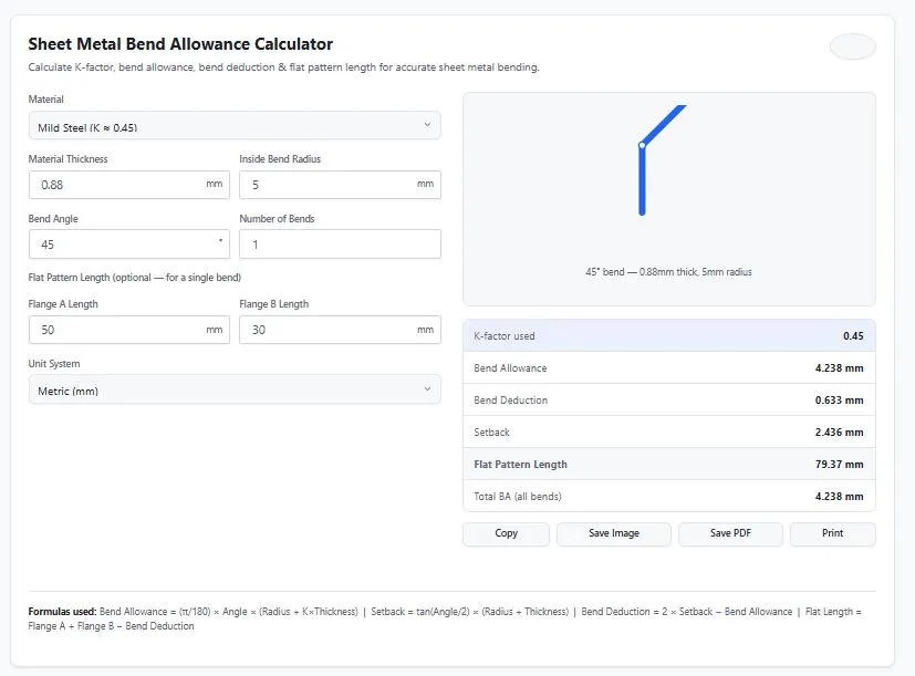
Table of Contents
Formula used: Bend Allowance = (π/180) × Angle × (Radius + K × Thickness)
Worked Example: A 90° Bend in 2 mm Mild Steel
Enter 2 mm thickness, 3 mm inside radius, 90°, the mild steel K-factor of 0.45, and flanges of 50 mm and 30 mm:
- Bend Allowance = (π/180) × 90 × (3 + 0.45 × 2) = 1.5708 × 3.9 = 6.126 mm
- Setback = tan(90° ÷ 2) × (3 + 2) = 1 × 5 = 5 mm
- Bend Deduction = 2 × 5 − 6.126 = 3.874 mm
- Flat Pattern Length = 50 + 30 − 3.874 = 76.13 mm
With 5 identical bends, the total bend allowance is 6.126 × 5 = 30.63 mm.
How the Bend Angle Changes the Numbers
Same material (2 mm, 3 mm radius, K = 0.45), different bend angles:
| Bend Angle | Bend Allowance | Setback | Bend Deduction |
|---|---|---|---|
| 30° | 2.042 mm | 1.340 mm | 0.637 mm |
| 45° | 3.063 mm | 2.071 mm | 1.079 mm |
| 60° | 4.084 mm | 2.887 mm | 1.689 mm |
| 90° | 6.126 mm | 5.000 mm | 3.874 mm |
| 120° | 8.168 mm | 8.660 mm | 9.152 mm |
The angle here is the angle the metal is bent through, so a standard square corner is 90°.
How Much Does the K-Factor Matter?
For the 90° example above (flanges 50 + 30 mm), a small change in K moves the flat length:
| K-Factor | Bend Allowance | Flat Pattern Length |
|---|---|---|
| 0.35 | 5.812 mm | 75.81 mm |
| 0.40 | 5.969 mm | 75.97 mm |
| 0.45 | 6.126 mm | 76.13 mm |
| 0.50 | 6.283 mm | 76.28 mm |
A K-factor error of 0.10 shifts each bend by about 0.3 mm here. That is small for one bend, but on a part with many bends or tight tolerances it adds up, which is why a test bend is worth doing.
K-Factor Starting Points
K-factor is the position of the neutral axis as a fraction of the thickness. It is not a fixed material property. It also depends on the bend method (air bending, bottom bending, coining), the radius-to-thickness ratio and the tooling. The material presets use commonly accepted starting ranges:
| Material | Typical K-Factor |
|---|---|
| Mild steel | 0.44 – 0.46 |
| Aluminum | 0.35 – 0.42 |
| Stainless steel | 0.46 – 0.50 |
| Brass | 0.40 – 0.45 |
Choose the custom K-factor option when you have a verified value. For the underlying theory, see the SOLIDWORKS documentation on K-factor.
Shop Tips
- Bend a test piece and measure it, then back-calculate the real K-factor for your material, thickness and tooling.
- Take the inside radius from your die chart. It is mostly set by your tooling, not freely chosen.
- Measure flanges to the outside corner, so the flat length matches how you measure the finished part.
- Allow for springback separately. The calculator gives the flat geometry only.
- For parts with different angles or radii, calculate each bend on its own and add them up.
FAQs
How do I calculate bend allowance for sheet metal?
Multiply the bend angle (in radians) by the sum of the inside radius and K-factor times material thickness. The formula is: Bend Allowance = (π/180) × Bend Angle × (Inside Radius + K-factor × Thickness). This gives you the arc length of the neutral axis through the bend.
What is a good K-factor for mild steel?
Mild steel typically uses a K-factor between 0.44 and 0.46 for standard air bending. This range works well for most general fabrication, though the exact value can shift slightly based on bend radius and tooling.
What is the difference between bend allowance and bend deduction?
Bend allowance is the length added by the bend, measured along the neutral axis. Bend deduction is the amount you subtract from the sum of your flange lengths to get the correct flat pattern size. They're mathematically related: Bend Deduction = (2 × Setback) − Bend Allowance.
Does this bend allowance calculator work for aluminum and stainless steel?
Yes. This calculator includes preset K-factor ranges for Mild Steel, Aluminum, Stainless Steel, and Brass, plus a custom K-factor option for any other material or verified value you have.
How do I calculate flat pattern length before bending?
Add your two finished flange lengths together, then subtract the bend deduction: Flat Pattern Length = Flange A + Flange B − Bend Deduction. This calculator does this automatically once you enter your flange lengths.
Why does K-factor vary between materials and bend methods?
K-factor depends on how much a material stretches on the outside of a bend versus compresses on the inside. Softer, more ductile materials and different bending methods (air bending vs. bottom bending vs. coining) shift where the neutral axis sits, changing the K-factor even for the same material thickness.
Can I calculate bend allowance for multiple bends at once?
Yes. Enter the number of bends in your part, and this bend allowance calculator will show the total bend allowance across all bends, provided they share the same angle, radius, and material.
Is this bend allowance calculator free to use?
Yes, this calculator is completely free, requires no login or signup, and has no usage limits.
Quick Summary
Enter thickness, inside radius, angle, K-factor and flange lengths, and this bend allowance calculator returns bend allowance, bend deduction, setback and flat pattern length.
Disclaimer
The Bend Allowance Calculator and all information on this page are provided by BytePriva for general estimation and informational purposes only. K-factor values vary based on material grade, bend method (air bending, bottom bending, or coining), tooling, and bend radius-to-thickness ratio — the presets provided are commonly accepted industry starting points, not guaranteed values for your specific setup.
This tool is not a substitute for certified engineering calculations, experimentally verified K-factor testing, or professional CAD software analysis. Users are solely responsible for independently verifying all measurements, K-factor values, and calculations before using them for production cutting, tooling setup, structural applications, or any decision involving material cost, scrap risk, or safety-critical outcomes.
BytePriva, its owners, and contributors make no warranties, express or implied, regarding the accuracy, completeness, or reliability of this calculator or its results. To the fullest extent permitted by law, BytePriva shall not be held liable for any direct, indirect, incidental, or consequential loss, damage, or cost — including wasted material, scrapped parts, or production downtime — arising from the use of, or reliance on, this calculator or the information provided on this page.
By using this calculator, you acknowledge and agree to these terms. For production tooling setup or tight-tolerance parts, please verify K-factor experimentally or consult your press brake manufacturer's documentation.